Because of reasons I have recently acquired a Dell N2048P switch. It’s a very nice endpoint switch for which I happen to have multiple years of experience with due to my work and since it recently hit EoL, you can get used ones for dirt cheap on Ebay.
There’s only one problem: It’s loud as hell!
Granted, it also needs to potentially dissipate the heat from providing 600W of Power over Ethernet in total over it’s 48 PoE+ capable ports.
In my case I do want some of the PoE, but realistically I’ll not be using more than 50W in total.
So the solution seems simple: rip out the very loud Delta FFB03812HN fans (name rolls right of the tongue) and put in some Noctua NF-A4x20 FLX fans.
Let’s take a short look at the relevant stats of these two fans:
| Delta FFB03812HN | NF-A4x20 FLX | |
| Throughput | 25.9 m³/h | 9.4 m³/h |
| RPM | 12000RPM | 5000RPM |
| Noise Level | 55.5 dB(A) | 14.9 dB(A) |

Fortunately the Noctua fans come with the same connector as the original fans, but annoyingly the pinout is different. That’s easily fixed with a bit of fiddling though.
Put in the new fans, turn on the switch and everything seems to be working! Yay, we’re done right?
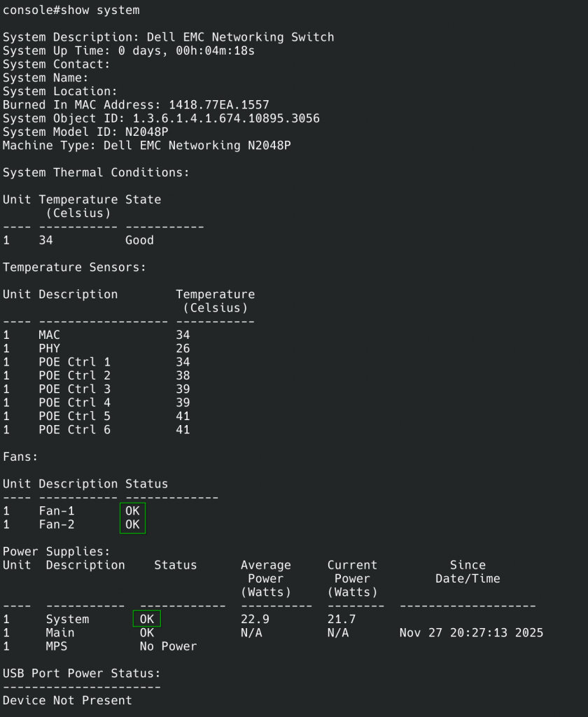
Let’s just give the system a short check to see if everything is fine and… uh oh:
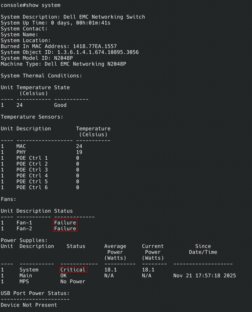
So it doesn’t like the new fans. I started testing to see if I broke it:
- Turn off switch, plug in old fans: It starts up, and is happy again. Good, I didn’t brick it
- Unplug old fans and plug in new fans while it is running: It continues to be happy! Yay
- Does it stay happy if I reboot with the new fans: No 🙁
So, it’s unhappy with the new fans. It seems to run just fine with them, but it will run them at full tilt all the time.
But why is it unhappy? What’s so offensive about the Noctua fans compared to the noisy Delta fans? Why is it happy with the Noctua fans if it boots up with the Delta fans?
After a bit of fiddling around, I noticed something: During boot, it will ramp the fans up to full speed for a few seconds and then (if it likes them) ramp them down to roughly a third of the speed.
Looking at the stats of the fans, it seems fairly obvious what it is doing: During boot, it runs the fans at full speed and checks the tachometer signal from them to see if they run at the expected speeds. The Noctua fans have a way lower max speed, so it just assumes they are broken.
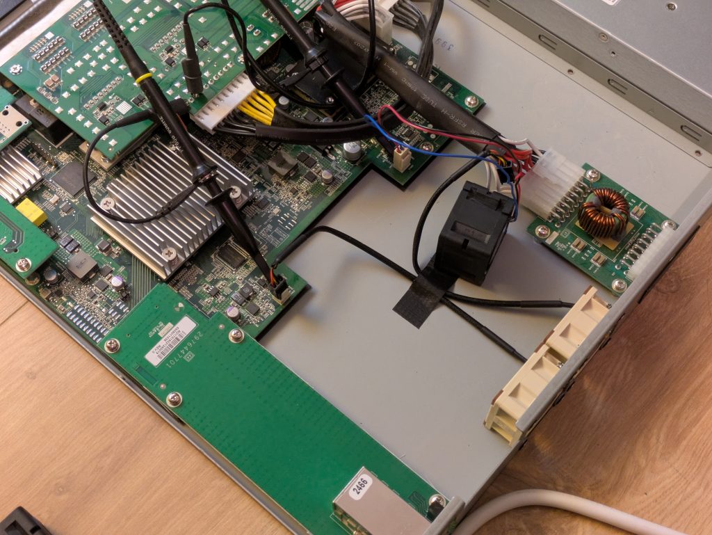
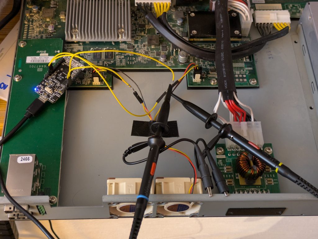
Let’s confirm this. After a bit of digging I found my cheap chinese USB-oscilloscope and hooked it up to the tachometer signals from the fans:
Reboot the switch and observe the signals during the ramp up:
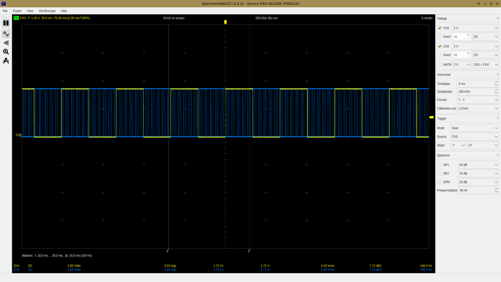
Not only is the Delta fan running faster, it also seems to use a slightly different tachometer signal. Going from 5000RPM to 12000RPM one would expect a ratio of 1:2.4, but it’s more than 1:5 here. Maybe the delta signal is doubled?
After pondering it a bit, I formulated a plan: Get an Arduino or a similar microcontroller and intercept the tachometer signal to trick the switch into thinking that the fans are running faster than they are.1
I dug through my pile of electronics and I found this ESP32 that used to have a display before I broke it (teehee):
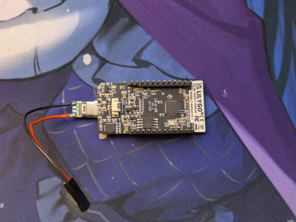
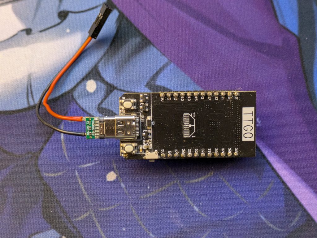
This should do fine. An ESP32 has a clock speed from 80MHz up to 240MHz which should be plenty to handle a signal less than a kilohertz.
One problem remains still: It needs 5V to run.
The fans are running on 12V so I cannot use those without a step down converter.
Most of the power rails in the switch are 54V for PoE power.
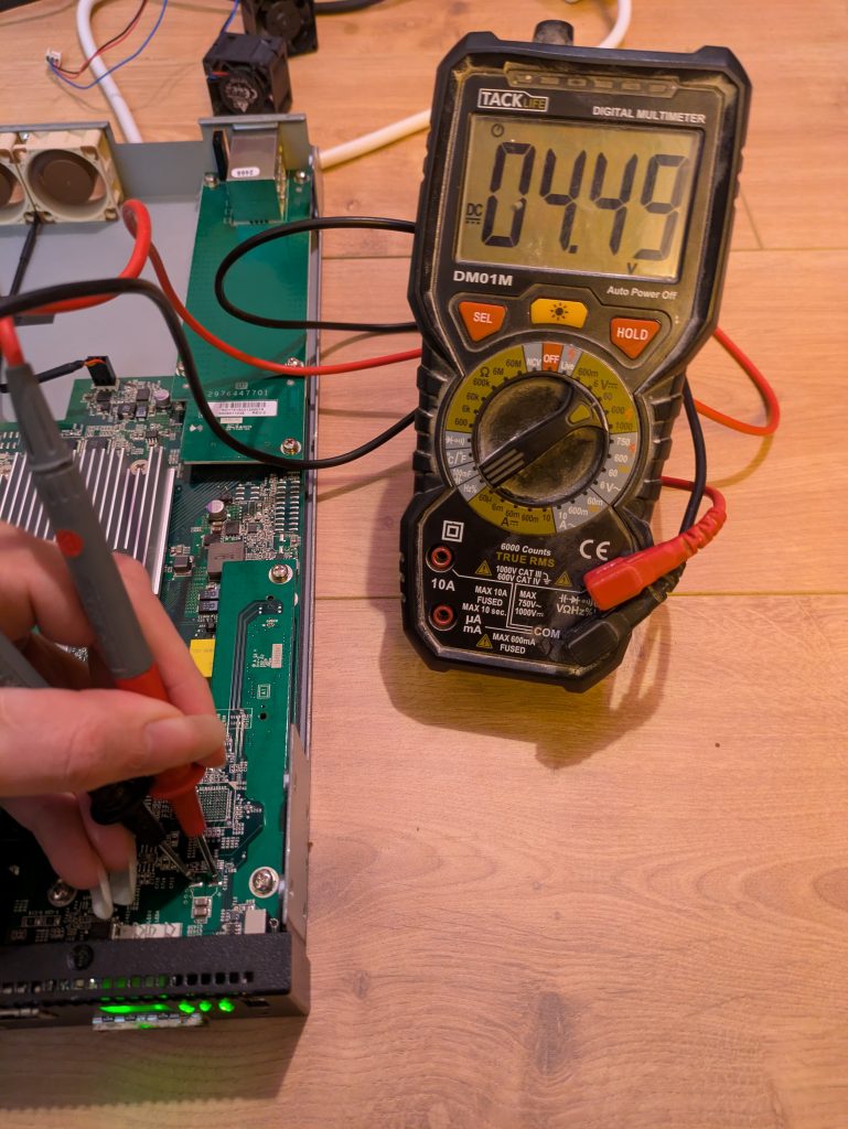
But then I realized: there’s a USB port at the front and it definitely needs 5V
So I started probing suspicious looking pads near the USB port and tadaa: We got 5V!
Now there’s just one thing missing: I have to program the microcontroller to actually do the thing.
Since I’m lazy (and I don’t really have to watch my power usage), I chose to use micropython2 instead of the ESP-IDF framework. It’s way easier to produce something that does the job.
After mucking around and messing up a few times, I cleaned up the code and this is what I ended with:
import machine
import esp32
import time

counterA = machine.Counter(0, machine.Pin(12, machine.Pin.IN), filter_ns=5000)
counterB = machine.Counter(1, machine.Pin(13, machine.Pin.IN), filter_ns=5000)

timerA = machine.Timer(0)
timerB = machine.Timer(1)
pinTimerA = machine.Pin(26, mode=machine.Pin.OUT)
pinTimerB = machine.Pin(25, mode=machine.Pin.OUT)

def flipPinA(t):
    pinTimerA.toggle()

def flipPinB(t):
    pinTimerB.toggle()

def updateTimer(timer, freq, callback):
    timer.deinit()
    if freq > 0:
        timer.init(freq=freq*2, callback=callback)

while True:
    countA = counterA.value(0)
    updateTimer(timerA, countA * 15, flipPinA)

    countB = counterB.value(0)
    updateTimer(timerB, countB * 15, flipPinB)

    time.sleep_ms(333)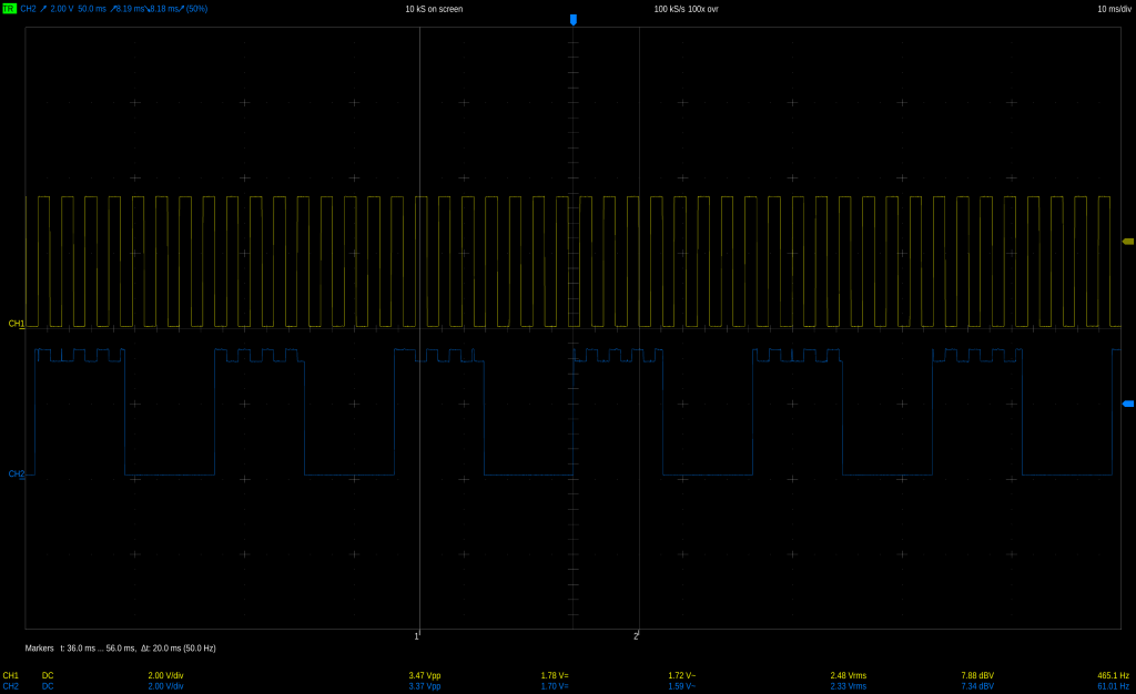
A few notes:
- I initially used the PWM class (because I am lazy) to generate the frequencies, but micropython occasionally seems to allocate a new hardware timer when you update the frequency which causes the code to crash sooner or later when you run out of hardware timer units.
Using the timers directly allows you to statically pick an ID sidestepping the problem entirely (it’s probably also better for performance, not that it matters). - The filter on the counters is important; the inside of the switch isn’t exactly radio silence so I get a lot of noise on the inputs. Without the filter I count pulses in the thousands instead of the roughly 20 I’d expect.
- I am counting pulses over 1/3 of a second to measure the incoming frequency. Longer means more accurate frequency measurement, shorter means faster update rate. It doesn’t matter much, but 1/3s seems a nice middle ground.
Now, I only need to put everything together: solder in the power cabling for the ESP, put heatshrink tubes on the connectors (I ran out of the plastic plugs) etc…

All that’s left to do is to turn the thing on and check if it works and, well, it does:
Now it’s happy and silent. Of course I’ll have to watch the thermals a bit when I actually rack the thing up, but it’ll be fiiiiine, right?